实例代码如下
/********************************** (C) COPYRIGHT *******************************
* File Name          : main.c
* Author             : WCH
* Version            : V1.0.0
* Date               : 2024/02/20
* Description        : Main program body.
*********************************************************************************
* Copyright (c) 2021 Nanjing Qinheng Microelectronics Co., Ltd.
* Attention: This software (modified or not) and binary are used for
* microcontroller manufactured by Nanjing Qinheng Microelectronics.
*******************************************************************************/

/*
 *@Note
 *TIM trigger ADC conversion routine:
 *ADC channel 2 (PC4) - injection group channel, TIM1 CH3 pin (PC3)  TIM trigger,
 *In this mode, an ADC conversion is triggered by an event on TIM1 CH3 TIM trigger, and a JEOC interrupt is generated after
 *the conversion is completed.
 *
 */

#include "debug.h"

/* Global Variable */

/*********************************************************************
 * @fn      ADC_Function_Init
 *
 * @brief   Initializes ADC collection.
 *
 * @return  none
 */
void ADC_Function_Init(void)
{
    ADC_InitTypeDef  ADC_InitStructure = {0};
    GPIO_InitTypeDef GPIO_InitStructure = {0};
    NVIC_InitTypeDef NVIC_InitStructure = {0};

    RCC_APB2PeriphClockCmd(RCC_APB2Periph_GPIOC, ENABLE);
    RCC_APB2PeriphClockCmd(RCC_APB2Periph_ADC1, ENABLE);
    RCC_ADCCLKConfig(RCC_PCLK2_Div6);

    GPIO_InitStructure.GPIO_Pin = GPIO_Pin_4;
    GPIO_InitStructure.GPIO_Mode = GPIO_Mode_AIN;
    GPIO_Init(GPIOC, &GPIO_InitStructure);

    ADC_DeInit(ADC1);
    ADC_InitStructure.ADC_Mode = ADC_Mode_Independent;
    ADC_InitStructure.ADC_ScanConvMode = DISABLE;
    ADC_InitStructure.ADC_ContinuousConvMode = DISABLE;
    ADC_InitStructure.ADC_ExternalTrigConv = ADC_ExternalTrigInjecConv_T1_CC3;
    ADC_InitStructure.ADC_DataAlign = ADC_DataAlign_Right;
    ADC_InitStructure.ADC_NbrOfChannel = 1;
    ADC_Init(ADC1, &ADC_InitStructure);

    ADC_InjectedSequencerLengthConfig(ADC1, 1);
    ADC_InjectedChannelConfig(ADC1, ADC_Channel_2, 1, ADC_SampleTime_9Cycles);
    ADC_ExternalTrigInjectedConvCmd(ADC1, ENABLE);

    NVIC_InitStructure.NVIC_IRQChannel = ADC_IRQn;
    NVIC_InitStructure.NVIC_IRQChannelPreemptionPriority = 0;
    NVIC_InitStructure.NVIC_IRQChannelSubPriority = 1;
    NVIC_InitStructure.NVIC_IRQChannelCmd = ENABLE;
    NVIC_Init(&NVIC_InitStructure);

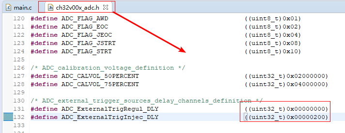
    ADC_ExternalTrig_DLY(ADC1, ADC_ExternalTrigInjec_DLY, 0x80);  /* external trigger sources delay time */
    ADC_Calibration_Vol(ADC1, ADC_CALVOL_50PERCENT);
    ADC_ITConfig(ADC1, ADC_IT_JEOC, ENABLE);
    ADC_Cmd(ADC1, ENABLE);

    ADC_ResetCalibration(ADC1);
    while(ADC_GetResetCalibrationStatus(ADC1));
    ADC_StartCalibration(ADC1);
    while(ADC_GetCalibrationStatus(ADC1));
}

/*********************************************************************
 * @fn      EXTI_Event_Init
 *
 * @brief   Initializes EXTI.
 *
 * @return  none
 */
void TIM1_PWM_In(u16 arr, u16 psc, u16 ccp)
{
    GPIO_InitTypeDef        GPIO_InitStructure = {0};
    TIM_OCInitTypeDef       TIM_OCInitStructure = {0};
    TIM_TimeBaseInitTypeDef TIM_TimeBaseInitStructure = {0};

    RCC_APB2PeriphClockCmd(RCC_APB2Periph_GPIOC | RCC_APB2Periph_TIM1, ENABLE);

    GPIO_InitStructure.GPIO_Pin = GPIO_Pin_3;
    GPIO_InitStructure.GPIO_Mode = GPIO_Mode_AF_PP;//
    GPIO_InitStructure.GPIO_Speed = GPIO_Speed_30MHz;
    GPIO_Init(GPIOC, &GPIO_InitStructure);

    TIM_TimeBaseInitStructure.TIM_Period = arr;
    TIM_TimeBaseInitStructure.TIM_Prescaler = psc;
    TIM_TimeBaseInitStructure.TIM_ClockDivision = TIM_CKD_DIV1;
    TIM_TimeBaseInitStructure.TIM_CounterMode = TIM_CounterMode_Up;
    TIM_TimeBaseInit(TIM1, &TIM_TimeBaseInitStructure);

    TIM_OCInitStructure.TIM_OCMode = TIM_OCMode_PWM1;
    TIM_OCInitStructure.TIM_OutputState = TIM_OutputState_Enable;
    TIM_OCInitStructure.TIM_Pulse = ccp;
    TIM_OCInitStructure.TIM_OCPolarity = TIM_OCPolarity_High;
    TIM_OC3Init(TIM1, &TIM_OCInitStructure);

    TIM_CCxCmd(TIM1, TIM_Channel_3, TIM_CCx_Enable);

    TIM_CtrlPWMOutputs(TIM1, ENABLE);
    TIM_OC3PreloadConfig(TIM1, TIM_OCPreload_Disable);
    TIM_ARRPreloadConfig(TIM1, ENABLE);
    TIM_SelectOutputTrigger(TIM1, TIM_TRGOSource_Update);
    TIM_Cmd(TIM1, ENABLE);
}


/*********************************************************************
 * @fn      main
 *
 * @brief   Main program.
 *
 * @return  none
 */
int main(void)
{
    SystemCoreClockUpdate();
    Delay_Init();
#if (SDI_PRINT == SDI_PR_OPEN)
    SDI_Printf_Enable();
#else
    USART_Printf_Init(115200);
#endif
    printf("SystemClk:%d\r\n", SystemCoreClock);
    printf( "ChipID:%08x\r\n", DBGMCU_GetCHIPID() );

    RCC_APB2PeriphClockCmd(RCC_APB2Periph_GPIOD, ENABLE);

    GPIO_InitTypeDef        GPIO_InitStructure = {0};
    GPIO_InitStructure.GPIO_Pin = GPIO_Pin_2;
    GPIO_InitStructure.GPIO_Mode = GPIO_Mode_Out_PP;//
    GPIO_InitStructure.GPIO_Speed = GPIO_Speed_50MHz;
    GPIO_Init(GPIOD, &GPIO_InitStructure);

    ADC_Function_Init();
    TIM1_PWM_In(4800,100,2400);
    while(1)
    {

    }
}

void ADC1_IRQHandler(void) __attribute__((interrupt("WCH-Interrupt-fast")));

/*********************************************************************
 * @fn      ADC1_IRQHandler
 *
 * @brief   ADC1_2 Interrupt Service Function.
 *
 * @return  none
 */
void ADC1_IRQHandler(void)
{

    if(ADC_GetITStatus(ADC1, ADC_IT_JEOC))
    {
        //printf("ADC Extline trigger conversion...\r\n");
        //ADC_val = ADC_GetInjectedConversionValue(ADC1, ADC_InjectedChannel_1);
        //printf("JADC-%04d\r\n", ADC_val);
        GPIO_SetBits(GPIOD, GPIO_Pin_2);
        GPIO_ResetBits(GPIOD, GPIO_Pin_2);
    }

    ADC_ClearITPendingBit(ADC1, ADC_IT_JEOC);
}
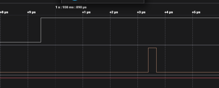
当延时设置为0x00时:
ADC_ExternalTrig_DLY(ADC1, ADC_ExternalTrigInjec_DLY, 0x00);
波形如下:

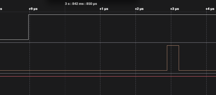
当延时设置为0x40时:
ADC_ExternalTrig_DLY(ADC1, ADC_ExternalTrigInjec_DLY, 0x40);
波形如下:

大约都是3.8us,与预期不符。
代码附件:
热门产品 :
CH585: 集成高速USB和NFC的蓝牙MCU

