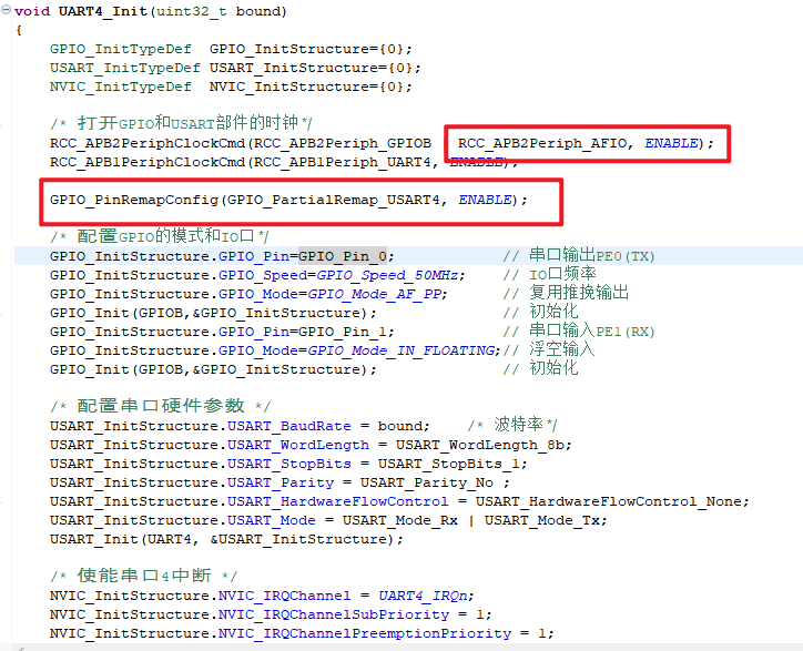
使用ch32v307的串口2中断和串口3中断,接收发送数据均无问题,但是添加串口4(也使用中断)后,串口2和串口3被影响不能正常工作。
串口2、串口3为USART,串口4为UART。
串口2初始化为
void USART2_init(void)
{
    GPIO_InitTypeDef  GPIO_InitStructure = {0};
    USART_InitTypeDef USART_InitStructure = {0};
    NVIC_InitTypeDef  NVIC_InitStructure = {0};

    RCC_APB2PeriphClockCmd(RCC_APB2Periph_GPIOA, ENABLE);
    //RCC_APB2PeriphClockCmd(RCC_APB2Periph_AFIO, ENABLE);
    RCC_APB1PeriphClockCmd(RCC_APB1Periph_USART2, ENABLE);

    /* USART2 TX-->A.2  RX-->A.3 */
    GPIO_InitStructure.GPIO_Pin = GPIO_Pin_2;
    GPIO_InitStructure.GPIO_Speed = GPIO_Speed_50MHz;
    GPIO_InitStructure.GPIO_Mode = GPIO_Mode_AF_PP;
    GPIO_Init(GPIOA, &GPIO_InitStructure);
    GPIO_InitStructure.GPIO_Pin = GPIO_Pin_3;
    GPIO_InitStructure.GPIO_Mode = GPIO_Mode_IN_FLOATING;
    GPIO_Init(GPIOA, &GPIO_InitStructure);

    USART_InitStructure.USART_BaudRate = 115200;
    USART_InitStructure.USART_WordLength = USART_WordLength_8b;
    USART_InitStructure.USART_StopBits = USART_StopBits_1;
    USART_InitStructure.USART_Parity = USART_Parity_No;
    USART_InitStructure.USART_HardwareFlowControl = USART_HardwareFlowControl_None;
    USART_InitStructure.USART_Mode = USART_Mode_Tx | USART_Mode_Rx;

    USART_Init(USART2, &USART_InitStructure);
    USART_ITConfig(USART2, USART_IT_RXNE, ENABLE);

    NVIC_InitStructure.NVIC_IRQChannel = USART2_IRQn;
    NVIC_InitStructure.NVIC_IRQChannelPreemptionPriority = 2;
    NVIC_InitStructure.NVIC_IRQChannelSubPriority = 1;
    NVIC_InitStructure.NVIC_IRQChannelCmd = ENABLE;
    NVIC_Init(&NVIC_InitStructure);

    USART_Cmd(USART2, ENABLE);
}
串口3初始化为:
void USART3_init(void)
{
    GPIO_InitTypeDef  GPIO_InitStructure = {0};
    USART_InitTypeDef USART_InitStructure = {0};
    NVIC_InitTypeDef  NVIC_InitStructure = {0};

    RCC_APB2PeriphClockCmd(RCC_APB2Periph_GPIOC, ENABLE);
    RCC_APB2PeriphClockCmd(RCC_APB2Periph_AFIO, ENABLE);
    RCC_APB1PeriphClockCmd(RCC_APB1Periph_USART3, ENABLE);

    USART_DeInit(USART3);

    // USART3  TX--C10  RX--C11
    GPIO_PinRemapConfig(GPIO_PartialRemap_USART3, ENABLE);

    GPIO_InitStructure.GPIO_Pin = GPIO_Pin_10;
    GPIO_InitStructure.GPIO_Speed = GPIO_Speed_50MHz;
    GPIO_InitStructure.GPIO_Mode = GPIO_Mode_AF_PP;
    GPIO_Init(GPIOC, &GPIO_InitStructure);
    GPIO_InitStructure.GPIO_Pin = GPIO_Pin_11;
    GPIO_InitStructure.GPIO_Mode = GPIO_Mode_IN_FLOATING;
    GPIO_Init(GPIOC, &GPIO_InitStructure);

    USART_InitStructure.USART_BaudRate = 115200;
    USART_InitStructure.USART_WordLength = USART_WordLength_8b;
    USART_InitStructure.USART_StopBits = USART_StopBits_1;
    USART_InitStructure.USART_Parity = USART_Parity_No;
    USART_InitStructure.USART_HardwareFlowControl = USART_HardwareFlowControl_None;
    USART_InitStructure.USART_Mode = USART_Mode_Tx | USART_Mode_Rx;

    USART_Init(USART3, &USART_InitStructure);
    USART_ITConfig(USART3, USART_IT_RXNE, ENABLE);

    NVIC_InitStructure.NVIC_IRQChannel = USART3_IRQn;
    NVIC_InitStructure.NVIC_IRQChannelPreemptionPriority = 2;
    NVIC_InitStructure.NVIC_IRQChannelSubPriority = 2;
    NVIC_InitStructure.NVIC_IRQChannelCmd = ENABLE;
    NVIC_Init(&NVIC_InitStructure);

    USART_Cmd(USART3, ENABLE);
}
串口4初始化为:
void uart4_init(void)
{
    GPIO_InitTypeDef  GPIO_InitStructure = {0};
    USART_InitTypeDef USART_InitStructure = {0};
    NVIC_InitTypeDef  NVIC_InitStructure = {0};

    RCC_APB2PeriphClockCmd(RCC_APB2Periph_GPIOB, ENABLE);
    //RCC_APB2PeriphClockCmd(RCC_APB2Periph_AFIO, ENABLE);
    RCC_APB1PeriphClockCmd(RCC_APB1Periph_UART4, ENABLE);

    /* UART4 TX-->B.1  RX-->B.0 */
    GPIO_InitStructure.GPIO_Pin = GPIO_Pin_1;
    GPIO_InitStructure.GPIO_Speed = GPIO_Speed_50MHz;
    GPIO_InitStructure.GPIO_Mode = GPIO_Mode_AF_PP;
    GPIO_Init(GPIOB, &GPIO_InitStructure);
    GPIO_InitStructure.GPIO_Pin = GPIO_Pin_0;
    GPIO_InitStructure.GPIO_Mode = GPIO_Mode_IN_FLOATING;
    GPIO_Init(GPIOB, &GPIO_InitStructure);

    USART_InitStructure.USART_BaudRate = 115200;
    USART_InitStructure.USART_WordLength = USART_WordLength_8b;
    USART_InitStructure.USART_StopBits = USART_StopBits_1;
    USART_InitStructure.USART_Parity = USART_Parity_No;
    USART_InitStructure.USART_HardwareFlowControl = USART_HardwareFlowControl_None;
    USART_InitStructure.USART_Mode = USART_Mode_Tx | USART_Mode_Rx;

    USART_Init(UART4, &USART_InitStructure);
    USART_ITConfig(UART4, USART_IT_RXNE, ENABLE);

    NVIC_InitStructure.NVIC_IRQChannel = UART4_IRQn;
    NVIC_InitStructure.NVIC_IRQChannelPreemptionPriority = 2; // 抢占优先级
    NVIC_InitStructure.NVIC_IRQChannelSubPriority = 3; // 子优先级
    NVIC_InitStructure.NVIC_IRQChannelCmd = ENABLE;
    NVIC_Init(&NVIC_InitStructure);

    USART_Cmd(UART4, ENABLE);
}
串口4使用两种声明均一样会影响串口2和串口3:
void USART2_IRQHandler(void) __attribute__((interrupt()));
void USART3_IRQHandler(void) __attribute__((interrupt()));
//void USART4_IRQHandler(void) __attribute__((interrupt()));
void UART4_IRQHandler(void) __attribute__((interrupt("WCH-Interrupt-fast")));

